motorized damper actuator wiring diagram
The spring return system provides constant torque to the damper with and without power applied to. To find wiring diagrams for actuators and control valves see the attached.

Msfd Actuator Pdf
Typical Damper Motor Schematic Fan Motor Damper Motor Second Damper Motor Tr ansformer Tr L3 L2 L1 For 3-Phase damper motor voltage should be the same between L 1 and L 2.
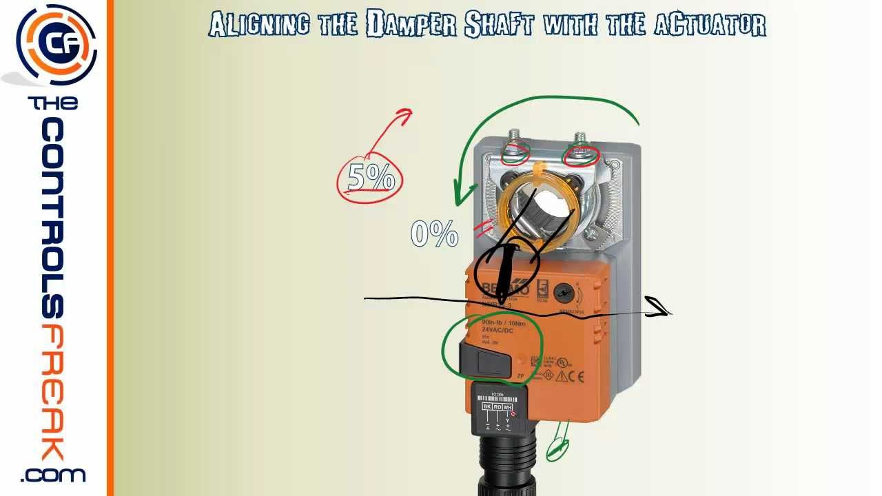
. For controlling air dampers with cross section up to 04 m² installed in various ventilation and air conditioning systems. Closed the actuator automatically power off after in place the. Place the actuator on the damper shaft with the front of the actuator accessible.
The terminal strip will accept wire sizes ranging from 14 to 22 AWG. The voltage of each specific model is indicated on a label that is affixed to the actuator see typical wiring diagrams. See wiring diagram figure 1.
RUS-L120-S Electric Spring-Return Actuator DESCRIPTION Ruskin model RUS-L120-S electric OnOff spring return actuator designed for factory mounting on dampers and operable louvers. To find wiring diagrams for actuators and control valves see the attached Wiring for Damper Actuators and Control Valves guide. 3 and 4 wiring diagrams.
Note that heaters use approximately 0 5 amps at 110 volts. Allow a minimum of 6 152 mm clearance behind the actuator for access to the wiring compartment. The label is on the front side.
Damper Motor Wiring Diagram wiring diagram is a simplified adequate pictorial representation of an electrical circuitIt shows the components of the circuit as simplified shapes and the capacity and signal friends amid the devices. Recommend installing a motorized damper between the HRVs supply air and the furnaces return air duct that closes when the ERV is not operating. Sept 2014 2 Actuator Components Figure 1.
WARNING Use caution when working in with or around valves and actuators. 1 wires from all actuators are tied together and tied to the negative leg of the control signal. HQ Series electric actuators are design to provide reliable and efficient operation of 90 quarter-turn valves dampers etc.
NOTICE 18 AWG minimum wire is recommended for all field wiring. Do not wire in. The damper is powered.
Runs less than 50 feet 15 m long require no shielded cable for the VDCmA control wiring. Place the actuator on the damper shaft so that the front of the actuator is accessible. RD connect with positive the BK connect with negative the valve.
Multiple actuators positioned by the same control signal may be powered from multiple transformers provided the following rules are followed. Wiring Diagram 240V 60 Hz FAN MOTOR SHUTTER MOTOR GRD240V POWER SUPPLY LINES SWITCH BLACK RED. The damper then returns to its normal position.
To ensure water and weather resistance install the cover gasket provided and use water-tight conduit fittings. Parts of the Rotary SmartX Actuator. Electric power to terminals 1 and 3 will cause the shaft to rotate clockwise.
Excess wiring outside the motor actuator wiring compartment. 1 wires from all actuators are tied together and tied to the negative leg of the control signal. An anti-rotation bracket is included with the actuator.
Actuators can be mounted directly to a damper or louver shaft from 34 to 1 116 inch 19 to 27 mm diameter with a universal clamp. The damper blade is powered by a VAC motor with spring return on power loss. Actuators can be wired in parallel.
For single phase application disregard L 3. A wiring diagram usually gives guidance approximately the relative position and covenant of devices and terminals on the devices to help in building or. BK connect with positive the RD connect with negative the valve.
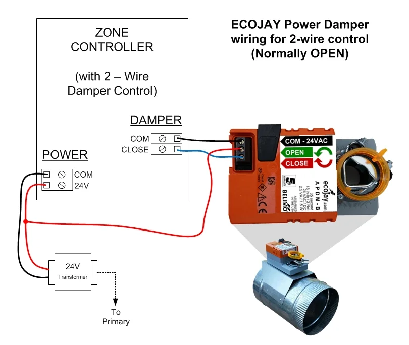
Damper motors may be available in 115 230 and 460 volt models. CR2 01 Wiring Diagram 2 wires control 1. If you are planing to replace the zone controller with SmartZone this diagram is NOT necessary.
Locate the actuator in a weather-protected area. Slide the actuator onto the damper shaft positioning the tab on the anti-rotation bracket midway into the slot at the bottom of the actuator. INSTALLATION INSTRUCTIONS PARTS LIST BACKDRAFT DAMPER AND CEILING SHUTTER MOTOR MODELS 411 610-A 611 SPECIFICATIONS.
Valve remains fully closed position. Pack is equipped with actuator motor bracket linkage and mounting hardware fasteners. The damper motor has a 24 Vac 5060 cycle 6 VA rating.
The angle of rotation is proportional to the control signal. Connect power to the terminal block according to the schematic wiring diagram inside the actuator cover. Damper Motor 24 VAC Transformer COM NO HRV Furnace.
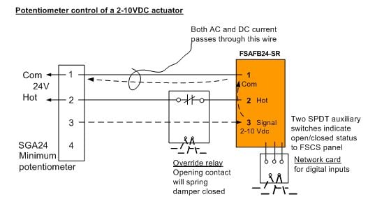
Minimum 34 diameter shaft and parallel wiring. Operation The EF24-S series actuators provide true spring return operation for reliable failsafe application and positive close off on air tight dampers. A 0 to 10 Vdc position feedback output signal is available between wire 9 U and wire 2 G0 to monitor the position of the damper motor.
INTAKE DUCT AND MOTORIZED DAMPER Disconnect electrical power before wiring the FAVS to the equipment. Wire type and wire installation tips. Open the actuator automatically power off after in place.
The spring-return ARD damper requires 24 Vac to the two motor leads to power the damper. Do not open the actuator. Wire type and wire installation tips.
The wiring diagram below shows how to connect the Ecojay Power Damper to an older zone panel that is only designed to work with 2-wire dampers. If desired add a standard electrical box to the wiring compartment of the motor actuator as shown in Figure 8. Multiple actuators positioned by the same control signal may be powered from multiple transformers provided the following rules are followed.
The transformers are properly sized. For actuator wiring information and diagrams refer to belimo wiring guide. 3 and 4 for motor wiring hookups.
The motor full load current is noted on the nameplate of the actuator. A continuous 0 to 10 Vdc signal from a controller to wire 8 Y operates the damper actuator. The label is on the front side.
Can a 2-10 VDC feedback signal be converted to. The damper motor nameplate voltage should be verified. You may also choose to use a Fantech ERV that uses a recirculation defrost that incorpo-rates an outdoor air damper.
For Variable Air Volume applications that use an M9108 Series actuator secure the coupler to the shaft with the damper in the fully open position to avoid damaging the open position end. Actuators input and output wiring with suitable flexible conduit. The minimum damper drive shaft length is 34-inch 20 mm.
Multiple ARD can be wired in parallel. Observe the service envelope around the actuator as shown in Figure 13. If the damper fails to open properly check for one of the following causes.
Figure 2 Installation 611. Avoid running low voltage control wiring in the. On dual voltages motor packs be sure to connect the proper motor leads for the correct voltage and insulate any unused wire.
Electric power to terminals 1 and 2 will cause the shaft to rotate counterclockwise. The transformers are properly sized. Dampers Install the actuator and the damper linkage so that 180 of.
Wiring a Motor See Fig.
A Method Of Damper Control For Corridor Ventilation And Smoke Extraction
Hvac Damper Zoningsupply Com Zone Control News Info

Ductwork Zone Dampers Airflow Controls Guide To Zone Dampers For Heating Cooling Air Duct Controls How To Install Use Manual Or Automatic Hvac Zone Dampers

Electrical Actuators Vanco Flow Control

Belimo Nm230a S Damper Actuator For Hvac System With Integrated Auxiliary Switch And Control By Open Close Or 3 Point Buy Belimo Nm230a S Damper Actuator Nm230a S Damper Actuator For Hvac System Spring Return Damper Actuator Product
Quick Tip To Make Sure Your Belimo Actuator Seals Your Damper Closed Youtube
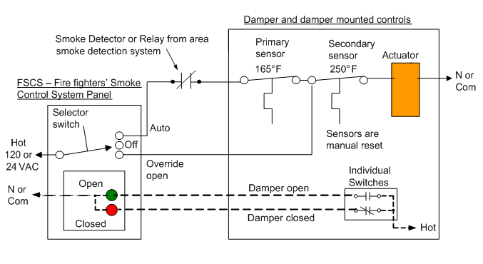
Code Required For Testing Of Fire Smoke And Combination Dampers

Lmb24 Belimo Modulating 24v Young Regulator
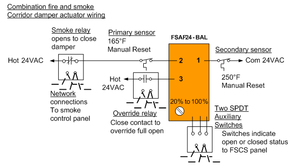
Modulating Control Of Fire Smoke Dampers In Smoke Control
Modulating Control Of Fire Smoke Dampers In Smoke Control
The 1 Asked Question About Fire And Smoke Dampers

Hvac 6nm 230v Motorized Damper Actuator Modulating Coowor Com
Modulating Control Of Fire Smoke Dampers In Smoke Control

Motors Disconnects Drives And Controls Oh My 2021 03 31 Engineered Systems Magazine
Electric Actuator For Motorized Dampers Electric Butterfly Valves Buy Butterfly Valves Motorized Dampers Electric Actuator Product On Alibaba Com

Msfd Actuator Pdf

General Damper Actuator 4nm 0 10v 4 20ma Modulating For Operation Of Air Control Dampers In Hvac System Adc24v Ac100 240v Air Control Dampers Air Controlactuator Control Module Aliexpress
S2024 2pos Sw2

Webinar Belimo Fire Smoke Damper Actuator Replacement Instructions Youtube